- info@unimetgauges.com
- +91 7620953505
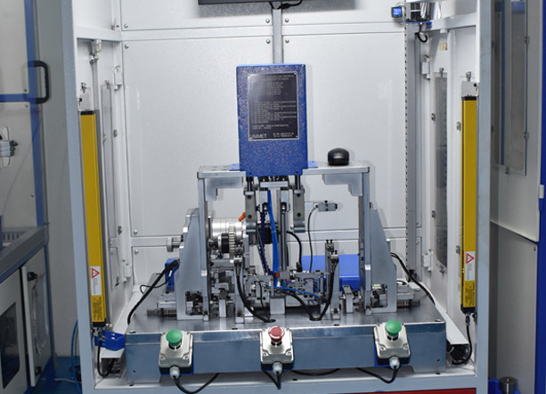
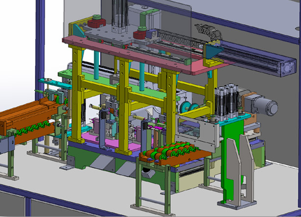
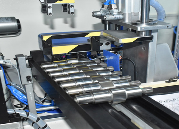
Unimet Auto Gauging systems are used to measure the critical parameters of a given component using automation such as a gantry loader. Today, we present our Auto Gauging System for Oil Pump Shaft. The component Loading & Unloading is done automatically - From the Feeder.
We at UNIMET Gauges Pvt Ltd bring expertise in Auto Gauging covering multiple aspects such as Automated gauging for shafts, gears, and diff cases at various levels, We provide Automated gauging for all the components with numerous static and dynamic parameters.
Examples of such Dynamic / static Parameters are but are not limited to
- Outer diameters at multiple levels
- Tapers at outer diameters
- Runout for outer diameter
- Parallelism w.r.t given reference
- Distances at given places
- ODs at multiple places
The Automated gauging system has the following benefits
- Effort saving
- No need for specialized d skills for operators
- Elimination of Human Error
- No missing the parameters
- Availability of data for SPC
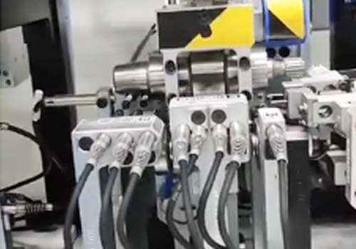
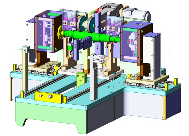
Auto Gauging System – Oil Pump Shaft
This Fixture is used to measure the following parameters
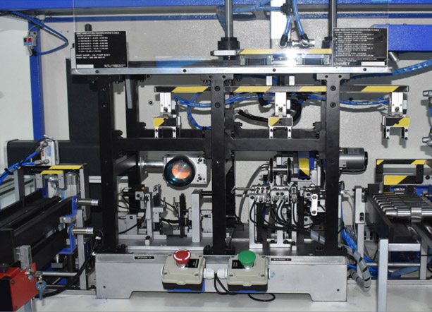
- Station-I Dynamic Parameters
OD1 At Level 1
OD1 At Level 2
Taper At OD1
OD2 At Level 1
OD2 At Level 2
Taper At OD2
OD3
Runout of OD3 w.r.t D & E Within 0.020 mm
Taper At Taper End
CAM Parallelism w.r.t D & E Within 0.010mm
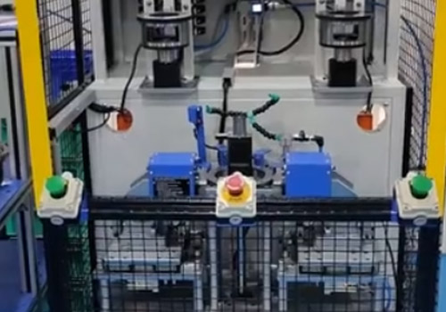
- Station-II Static Parameters
Distance 1
Distance 2
Distance 3
Distance 4
Distance 5
OD5
This Fixture is used to measure the following parameters
- Station Dynamic Parameters
OD1 At Level 1
OD1 At Level 2
Taper At OD1
OD2 At Level 1
OD2 At Level 2
Taper At OD2
OD3
Runout of OD3 w.r.t D & E Within 0.020 mm
Taper At Taper End
CAM Parallelism w.r.t D & E Within 0.010mm
- Station-II Static Parameters
Distance 1
Distance 2
Distance 3
Distance 4
Distance 5
OD5 - SPC System to gather real-time statistical data
- Reject and Rework bins to segregate the tested components
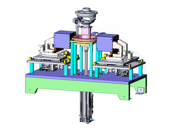
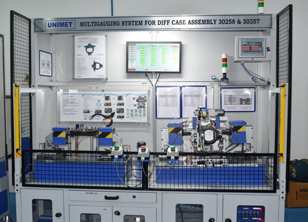
Auto Gauging System – Differential Case OP40
This Fixture is used to measure the following parameters
- ID1
- ID2
- Distance 1
- Distance 2
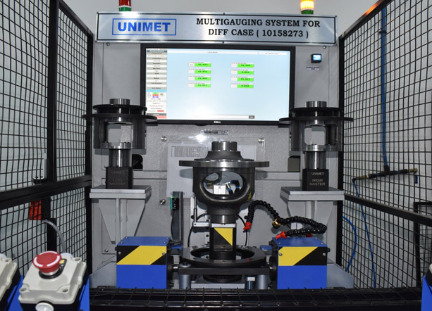
Auto Gauging System – Differential Case OP10 and OP20
This Fixture is used to measure the following parameters
- ID1
- STEP ID2
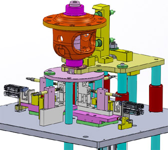
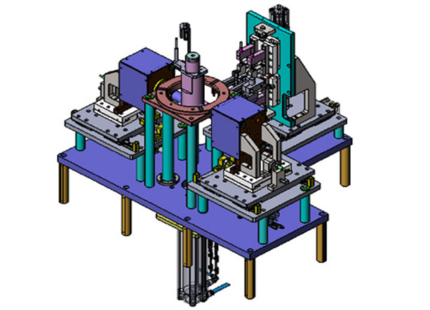
Auto Gauging System – Differential Case OP30
This Fixture is used to measure the following parameters
- Tr. OD1
- Tr. ID1
- Runout of ID1 Wrt TR. OD1 & TR. OD2
- Tr. OD2 F/S
- Tr. ID2 F/S
- Ring Gear OD3
- Tr. Length F/S
- Tr. Length R/S
- F/S Shoulder To Flange Face Length
- Shoulder To Shoulder Distance
- Total Length
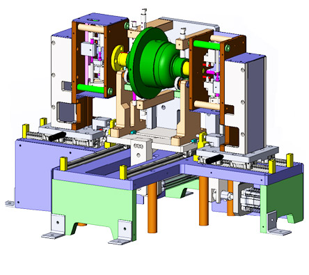
Auto Gauging System – Differential Case OP50
This Fixture is used to measure the following parameters
- Internal distance 1 from cross bore to side gear face-top side
- Parallelism of cross bore to side gear face top side within 0.080 mm
- Internal distance 2 from cross bore to side gear face bottom side
- Parallelism of cross bore to side gear face bottom side within 0.080 mm
Auto Gauging System – Rotor Shaft
This Fixture is used to measure the following parameters
- OD1
- OD2
- OD2 Runout WRT OD1-OD2
- OD3
- OD4 At 3 Places
- OD4 Ovality At Level 1
- OD5
- Runout Of OD5 Wrt OD1-OD2
- OD6
- Runout Of OD6 Wrt OD1-OD2
- OD7
- Runout Of OD6 Wrt OD1-OD2
- ID1
- ID2
- Face Runout W.R.T. OD1-OD2
- Face Runout W.R.T. OD1-OD2
- Distance 1
- Distance 2
- Distance 3
- Distance 4
- Distance 5 Grove Width
- Distance 6
- Distance 7